![]()
![]()
![]()

|
|
|
|
Should I keep the mass airflow meter screen on? Actually the screen is there for a reason - hence the stalls experienced with
removing it. The screen is actually there to help remove the turbulence
coming in through the upstream inlet. It does a rough job of "straightening" the
airflow so that the air meter element will read an accurate amount of airflow.
With swirls and backflows over the element, an incorrect air mass reading will
be measured. V8's inherently are not susceptible to backflow
regions unlike 4 cylinders since
V8’s intake pulses are at shorter intervals so that reduces the chance of
measurement error some.
Is it necessary to disconnect the battery after catback install or any other modification? No. Clearing all of the KAM does nothing to "speed-up" learning. It just bases out everything - adaptive fuel trim, adaptive idle speed air trim, returnless fuel adaptive, etc. The car is always adapting when it gets warmed up (under the right entry conditions). This is Car myth #1 out there...
How does the all-speed traction control system (TCS) work on my car? The primary purpose of the traction control system is to control wheel slip in a manner that provides a good compromise between vehicle stability and acceleration. The need for traction control follows from understanding tire force generation characteristics. Tire lateral and longitudinal forces are functions of wheel slip, which is proportional to the difference between driven and non-driven wheel speeds. Wheel slip is defined as:
Typical tire force versus slip curves are shown in Figure 1.
Figure 1. Lateral Force and Tractive Force Trends Versus Drive Wheel Slip Note that with large slips, or "spins", both the tractive (longitudinal) and, more significantly, lateral force generation capabilities are significantly reduced. Thus, the main TCS objective is to maintain tire slip within the circled region typically around 15 to 20% slip, to obtain the best compromise between directional control and forward acceleration. There are primarily two types of wheel slip control techniques: low-speed and all-speed TCS. Most automotive manufacturers offer low–speed and all–speed traction control systems. Low–speed TC systems use only brake pressure via the ABS system to control wheel slippage. However, because of brake durability concerns, low–speed systems are generally disabled above speeds of approximately 30 MPH. All–speed traction control systems use engine intervention to reduce engine torque output in addition to brake pressure control. This system is effective throughout the vehicle’s entire speed range. With an all-speed system, the ABS/TCS electronic control module continuously monitors each individual wheel speed. When it sees wheel slip, which is defined as the driven wheel speed(s) exceeding the non–driven wheel speed, it calculates a desired wheel (or engine) torque value which is necessary to decelerate the wheel. The software algorithm necessary to calculate an accurate desired wheel torque is very involved. When the strategy detects wheel slip, several actions need to be taken. First, the algorithm must determine what type of surface the vehicle is operating on (ice, snow, gravel, dry pavement) so that the correct control gains are applied. A very crude calculation can be made to approximate the surface coefficient of friction, m:
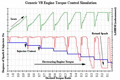
Tw = Wheel Torque From PCM Calculation Fx = Tractive Force N = Wheel Load r = Wheel Radius By comparing the wheel speeds of the each driven wheel, the software can also determine if the vehicle is on a split-mu surface. Filters reject wheel speed acceleration due to potholes, road bumps, and tire chirps (false TCS events). In order to account for changes in road surface characteristics (high to low m or low to high m transitions) and driver demand, the module updates torque requests at approximately 10 milliseconds whereas the engine controller updates the torque request every 60 milliseconds. The module then transmits this wheel torque value to the Powertrain Control Module. Simultaneously, the brake pressures are modulated via the ABS controller at the driven wheel(s) to help reduce wheel slip flares. The PCM calculates its current engine torque and converts it to a wheel torque value by applying the torque multiplication effect of the torque converter (for automatic transmissions), transmission gear, and final drive ratio while accounting for inertial losses The torque data are transmitted back to the ABS/TCS module to provide the current system torque status. The TCS module re-evaluates the wheel slip and sends out a new request. This loop continues until the TCS event is over. Torque Reduction Methodologies There are various methods to reduce and control the engine torque output. Throttling methods such as series throttle or secondary throttle systems use an addition throttle plate upstream of the primary (driver controlled) throttle plate thus effectively choking the engine. Electronic throttle operates in a similar fashion except that there is only a single plate that overrides driver demand when a torque reduction request is made. This method of throttling the engine has relatively slow transient response since you have to deal with manifold filling and emptying airflow dynamics. A more sophisticated (and increasingly more common) system uses air/fuel enleanment, fuel injector cutout, and spark retard to reduce engine torque output. This approach is attractive because it is relatively inexpensive since it uses existing engine hardware, has fast transient response, and provides full torque reduction capacity. Figure 4 illustrates a torque control simulation for a generic V8 engine using this system.
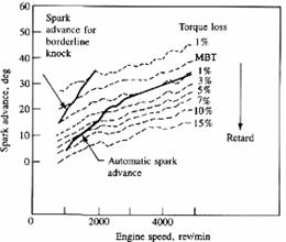
Figure 4. Engine Torque Reduction Using Air/fuel, Fuel Injector Cutout, and Spark Retard Figure 5 shows the typical torque response of an engine as the spark timing is retarded from MBT spark advance at various engine speeds. MBT spark timing is defined as the spark timing that results in the greatest torque output of the engine at a single engine speed and load point. Retarding spark timing from MBT moves the peak pressure to later in the power stroke and reduces the magnitude of the peak pressure. This reduces the work transferred to the piston resulting in less torque output.
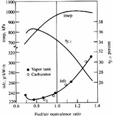
Figure 5. Torque Loss with Spark Retard Figure 6. Affect of A/F Figure 6 shows how the engine responds as the A/F ratio is varied around stoichiometry. Indicated Mean Effective Pressure (IMEP) is proportional to the torque output. Increasing the A/F ratio past stoichiometry (lean) decreases the work produced from combustion because the excess air dilutes the mixture, decreasing combustion temperatures and reducing the peak pressure from combustion.
Is there a way to desensitize the knock sensor system on the Mach1? Can I install resistors in series to tune them?
The best way to
desensitize the knock sensors is to simply rechip it the car. I can easily
reduce either the individual cylinder threshold tables or even easier reduce the
retard limit versus engine speed and load. I have done this on my car.
I am about to try out a C&L setup including the larger MAF on my vehicle
and want to baseline it on the dyno. Can I make a change back to the
K&N setup immediately following the dyno run with the C&L?
Are there any concerns relating to dyno tuning at sea level and then operating the vehicle at high altitude?
There is no issue with running at high altitude versus sea level. The
airmeter measures lower airmass at altitude, the inferred barometric pressure
algorithm calculates accordingly, and fuels accordingly. |
|
|